
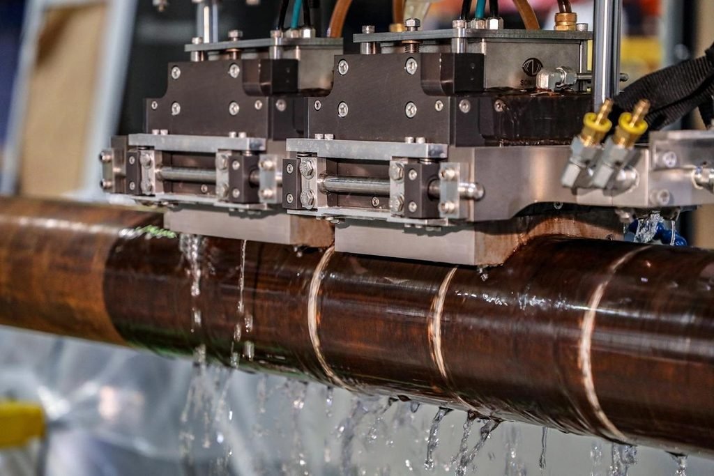
1. What Is Uneven Wall Thickness in Steel Pipes?
Uneven wall thickness refers to a condition in which the actual wall thickness of a steel pipe varies around its circumference or along its length.
Ideally, a steel pipe should have a uniform wall thickness throughout its cross-section and along its entire length, within the dimensional tolerances specified by the applicable product standard.
In actual manufacturing, however, variations can occur during billet piercing, rolling, welding, sizing and other production operations.
Uneven wall thickness is particularly important in pressure-bearing applications because the pipe’s minimum actual wall thickness directly affects its ability to withstand internal pressure.
There are three common forms of wall thickness variation:
1.1 Circumferential Wall Thickness Variation
Circumferential variation occurs when the wall thickness differs at different positions around the same pipe cross-section.
For example, one side of the pipe may have a wall thickness of 10.5 mm, while the opposite side measures only 9.2 mm.
This condition is commonly associated with pipe eccentricity.
1.2 Longitudinal Wall Thickness Variation
Longitudinal variation occurs when wall thickness changes along the length of the pipe.
A pipe may have an acceptable thickness near one end but become thinner or thicker toward the middle or opposite end.
This can result from unstable rolling conditions, inconsistent forming operations or manufacturing equipment deviations.
1.3 Localized Wall Thinning
Localized thinning refers to a limited area where the actual wall thickness is significantly lower than the surrounding material.
It may result from manufacturing defects, surface damage, excessive grinding, corrosion or erosion during service.
Unlike general dimensional variation, localized thinning can create a concentrated weak point.
2. Main Causes of Uneven Steel Pipe Wall Thickness
The causes of wall thickness variation differ between seamless and welded steel pipes.
For seamless pipes, billet quality, piercing conditions and rolling alignment are particularly important.
For welded pipes, strip thickness, forming accuracy, welding conditions and seam finishing can affect the final geometry.
2.1 Uneven Heating of Steel Billets
In seamless pipe manufacturing, steel billets are heated before piercing and rolling.
If the billet temperature is uneven, different areas may exhibit different deformation resistance.
Areas with higher temperatures generally deform more easily, while relatively colder areas may resist deformation.
This can lead to:
- Uneven metal flow.
- Irregular deformation.
- Unbalanced piercing.
- Inconsistent wall thickness.
Poor furnace temperature control, uneven heating and insufficient soaking time may contribute to this problem.
Prevention Measures:
- Maintain uniform billet heating.
- Monitor furnace temperature distribution.
- Control billet soaking time.
- Check billet surface conditions before piercing.
- Establish consistent heating procedures.
2.2 Improper Rotary Piercing Conditions
Rotary piercing is one of the most important manufacturing stages affecting the wall thickness of seamless steel pipes.
During piercing, a solid billet is transformed into a hollow shell using rotating rolls and a piercing plug.
If the plug is misaligned, worn or improperly positioned, the hollow shell may develop an eccentric wall structure.
Other contributing factors include:
- Incorrect roll gap settings.
- Improper plug geometry.
- Uneven billet rotation.
- Incorrect piercing temperature.
- Unstable piercing speed.
- Excessive deformation.
These conditions can produce a pipe with one side thicker than the other.
Prevention Measures:
- Regularly inspect piercing plugs.
- Maintain accurate roll alignment.
- Optimize piercing parameters.
- Monitor billet rotation and feeding conditions.
- Measure wall thickness after piercing.
2.3 Misalignment of Rolling Equipment
After piercing, the hollow shell passes through elongation and rolling operations.
Misalignment between rolls, mandrels and guide equipment may result in uneven deformation.
When the rolling force is not distributed uniformly, the pipe wall may become thicker on one side and thinner on the other.
Equipment wear can also cause dimensional instability.
Prevention Measures:
- Regularly calibrate rolling equipment.
- Inspect mandrel and roll conditions.
- Maintain correct equipment alignment.
- Monitor rolling force and dimensional changes.
- Perform routine equipment maintenance.
2.4 Improper Sizing and Reducing Operations
Sizing and reducing operations determine the final outside diameter and help control pipe dimensions.
Incorrect sizing settings may affect wall thickness distribution, especially when the pipe experiences uneven deformation.
Excessive reduction, incorrect roll positioning and unstable process parameters can contribute to local thickness variation.
Prevention Measures:
- Optimize sizing mill settings.
- Control reduction ratios.
- Monitor outside diameter and wall thickness simultaneously.
- Maintain consistent production parameters.
2.5 Inconsistent Raw Material Quality
The quality of the initial steel billet or strip also affects final pipe geometry.
Potential problems include:
- Uneven billet dimensions.
- Internal inclusions.
- Surface defects.
- Non-uniform material properties.
- Inconsistent strip thickness.
For welded pipes, variations in incoming strip thickness can be transferred into the finished pipe.
Prevention Measures:
- Inspect incoming raw materials.
- Verify material certificates.
- Control billet and strip dimensional tolerances.
- Reject unsuitable raw materials.
- Maintain batch traceability.
2.6 Improper Welding and Forming Conditions
For ERW and other welded steel pipes, wall thickness variation may be associated with strip thickness differences, forming instability and weld seam finishing.
Potential causes include:
- Uneven strip thickness.
- Incorrect forming roll alignment.
- Inconsistent welding conditions.
- Excessive internal or external weld bead removal.
- Improper sizing after welding.
Excessive scarfing of the internal weld bead can locally reduce the remaining wall thickness.
Prevention Measures:
- Control incoming strip thickness.
- Maintain forming roll alignment.
- Monitor welding parameters.
- Control internal and external bead removal.
- Inspect the weld area after finishing.
3. How Does Uneven Wall Thickness Affect Steel Pipe Pressure Performance?
Wall thickness is one of the most important parameters affecting the pressure resistance of steel pipes.
For a given material, diameter and internal pressure, reducing the pipe wall thickness increases the stress acting on the remaining material.
Uneven wall thickness creates a situation in which different areas of the same pipe experience different stress levels.
3.1 Increased Hoop Stress
When a steel pipe carries internal pressure, tensile stress develops around its circumference.
This is known as hoop stress or circumferential stress.
For a thin-walled cylindrical pipe, the approximate hoop stress can be expressed as:
[
\sigma_h=\frac{PD}{2t}
]
Where:
- (\sigma_h) = Hoop stress.
- (P) = Internal pressure.
- (D) = Pipe diameter.
- (t) = Wall thickness.
For a given pressure and diameter, hoop stress increases as wall thickness decreases.
Therefore, the thinnest area of an uneven pipe can experience higher hoop stress than the thicker areas.
For pressure design, this simplified equation should not replace the applicable ASME, B31, API or other governing design calculation.
3.2 Reduced Pressure-Bearing Capacity
The pressure-bearing capacity of a pipe depends on its material strength, dimensions and design factors.
When the actual wall thickness is lower than the specified nominal thickness, the pipe may have less pressure capacity than expected if the design calculation does not account for that reduction.
A localized thin area can become the controlling section for pressure integrity.
For this reason, the minimum permissible wall thickness is an important acceptance parameter.
3.3 Localized Yielding and Plastic Deformation
If the local stress exceeds the material’s yield strength, permanent deformation may occur.
Possible consequences include:
- Local bulging.
- Permanent dimensional changes.
- Local strain concentration.
- Reduced structural integrity.
The likelihood depends on the actual minimum thickness, material properties, pressure and loading conditions.
3.4 Increased Risk of Leakage and Rupture
Severe local thinning can increase the likelihood of pressure boundary failure.
If a thin region experiences excessive stress, it may eventually develop a leak or rupture.
This risk is particularly important in:
- High-pressure pipelines.
- Oil and gas transmission systems.
- Boiler piping.
- Chemical processing facilities.
- High-temperature service.
- Cyclic pressure applications.
3.5 Reduced Service Life
Uneven wall thickness may also reduce the remaining corrosion allowance at the thinnest location.
If corrosion or erosion occurs during service, an already thin area may reach its minimum allowable thickness sooner than the rest of the pipe.
This can lead to earlier inspection, repair or replacement requirements.
4. Example: How Wall Thickness Variation Changes Hoop Stress
Consider a hypothetical steel pipe with the following conditions:
- Outside diameter: 219.1 mm.
- Internal pressure: 10 MPa.
- Material: Carbon steel.
- Nominal wall thickness: 10 mm.
For illustration, the thin-wall hoop stress equation can be used to compare different wall thicknesses.
The mean diameter is approximately the average of the inside and outside diameters.
4.1 Comparison of Different Wall Thicknesses
| Actual Wall Thickness | Approximate Hoop Stress |
|---|---|
| 10.0 mm | 104.3 MPa |
| 9.5 mm | 109.8 MPa |
| 9.0 mm | 115.8 MPa |
| 8.5 mm | 122.6 MPa |
| 8.0 mm | 130.4 MPa |
As the wall thickness decreases from 10 mm to 8 mm, the approximate hoop stress increases by about 25%.
This demonstrates why the minimum wall thickness is more important for pressure integrity than simply checking the average wall thickness.
Important: These are illustrative thin-wall calculations using mean diameter. They are not allowable pressure ratings or code-compliant design results. Actual pipe design must consider the governing code, material allowable stress, temperature, weld joint factors, corrosion allowance, dimensional tolerances and other applicable factors.
5. Wall Thickness Tolerance vs Wall Thickness Eccentricity
These two concepts are often confused during steel pipe inspection.
5.1 Wall Thickness Tolerance
Wall thickness tolerance refers to the permitted deviation between the actual wall thickness and the specified nominal thickness.
For example, a product standard may allow a certain positive or negative deviation.
A pipe can have a certain degree of thickness variation and still comply with the applicable dimensional tolerance.
5.2 Wall Thickness Eccentricity
Eccentricity refers to the difference between the maximum and minimum wall thickness measured around the same cross-section.
A commonly used calculation is:
[
E=\frac{t_{\max}-t_{\min}}{t_{\max}}\times100%
]
Where:
- (E) = Eccentricity percentage.
- (t_{\max}) = Maximum measured wall thickness.
- (t_{\min}) = Minimum measured wall thickness.
For example:
- Maximum wall thickness = 10.5 mm.
- Minimum wall thickness = 9.0 mm.
Then:
[
E=\frac{10.5-9.0}{10.5}\times100%
=14.29%
]
This calculation describes the relative difference between the thickest and thinnest measurements.
It should not be confused with the percentage deviation from nominal wall thickness.
5.3 Does Every Pipe Need the Same Eccentricity Limit?
No.
The allowable wall thickness variation depends on the applicable product standard, manufacturing method, pipe dimensions and purchase requirements.
For example, API 5L provides separate wall thickness tolerance requirements for seamless and welded pipes.
Certain project-specific supplementary requirements may also establish additional eccentricity limits, particularly at pipe ends.
Buyers should not apply a single universal eccentricity percentage to all steel pipes.
6. Wall Thickness Requirements Under Common Steel Pipe Standards
Different standards establish different dimensional tolerances.
The following standards are relevant to wall thickness control.
6.1 API 5L
API 5L covers seamless and welded line pipe used in petroleum and natural gas pipeline transportation systems.
It specifies dimensional tolerances for:
- Outside diameter.
- Wall thickness.
- Length.
- Straightness.
- Out-of-roundness.
The tolerances differ according to pipe type and dimensions.
6.2 ASTM A106
ASTM A106 covers seamless carbon steel pipe for high-temperature service.
Wall thickness requirements must comply with the applicable dimensional requirements and the specified pipe size and schedule.
6.3 ASTM A53
ASTM A53 covers black and hot-dipped zinc-coated welded and seamless steel pipe.
Different manufacturing types have applicable dimensional and wall thickness requirements.
6.4 ASTM A335
ASTM A335 covers seamless ferritic alloy steel pipe for high-temperature service.
Wall thickness and dimensional requirements must be verified against the applicable product specification.
6.5 ASME B36.10M
ASME B36.10M provides standard dimensions for welded and seamless wrought steel pipes.
It includes nominal pipe sizes, outside diameters and wall thickness schedules.
It is important to distinguish standard dimensional tables from manufacturing acceptance tolerances.
The nominal wall thickness shown in a pipe schedule does not mean every measured point must have exactly that thickness.
7. How to Inspect Steel Pipe Wall Thickness
Accurate inspection is essential for identifying wall thickness variation before pipes are accepted or installed.
Several methods are commonly used.
7.1 Ultrasonic Thickness Testing (UT)
Ultrasonic thickness measurement is one of the most widely used nondestructive methods for steel pipe wall thickness inspection.
A probe sends ultrasonic pulses into the pipe and measures the time required for the reflected signal to return.
Wall thickness is calculated using the measured sound travel time and the calibrated sound velocity of the material.
Advantages include:
- Nondestructive measurement.
- Direct thickness readings.
- Ability to inspect internal and external wall conditions.
- Suitability for production inspection.
- Potential for automated circumferential and longitudinal scanning.
The equipment must be calibrated for the material and measurement conditions.
7.2 Mechanical Thickness Measurement
Mechanical methods such as calipers and suitable thickness gauges can be used to measure accessible pipe ends and cut sections.
They are useful for checking local dimensions and validating ultrasonic measurements.
However, they may not be suitable for measuring every location along a long finished pipe.
7.3 Laser Measurement Systems
Laser measurement systems are used to measure pipe geometry, including outside diameter, roundness and certain dimensional characteristics.
They are particularly useful in automated production lines.
Laser measurement of the outside surface alone does not directly establish the internal wall position. Additional measurement or combined sensing methods are needed to determine wall thickness.
7.4 Metallographic Examination
Metallographic examination involves cutting and preparing a pipe sample to observe its cross-section.
It can be used to evaluate:
- Actual wall thickness distribution.
- Pipe eccentricity.
- Weld seam geometry.
- Local thinning.
- Material microstructure.
It is particularly useful when investigating manufacturing defects or validating nondestructive measurements.
8. How Manufacturers Control Uneven Wall Thickness
Effective wall thickness control requires monitoring throughout the manufacturing process.
8.1 Raw Material Inspection
Manufacturers should verify the dimensional quality of billets, steel strips and other incoming materials.
8.2 Process Parameter Control
Heating temperature, piercing conditions, rolling speed and sizing parameters should be maintained within established process windows.
8.3 Equipment Calibration
Rolling mills, piercing plugs, guide shoes, sizing equipment and measurement instruments should be regularly inspected and calibrated.
8.4 Online Thickness Monitoring
Automated ultrasonic or laser-based measurement systems can help detect dimensional deviations during production.
Online monitoring allows manufacturers to identify trends and adjust equipment before producing large quantities of nonconforming pipes.
8.5 Final Inspection
Finished pipes should undergo the dimensional and testing procedures specified by the relevant product standard and purchase order.
Inspection should include measurements at multiple circumferential positions and appropriate locations along the pipe length.
9. What Should Buyers Check Before Purchasing Steel Pipes?
Wall thickness control is an important part of steel pipe procurement.
Buyers should confirm the following items before accepting a shipment.
9.1 Specified Wall Thickness
Confirm the nominal wall thickness, pipe schedule and applicable dimensional standard.
9.2 Minimum Permissible Wall Thickness
Confirm the negative wall thickness tolerance and any additional project requirements.
Do not rely only on average wall thickness.
9.3 Circumferential Thickness Variation
Request measurement records showing the maximum and minimum wall thickness around the circumference where required.
9.4 Longitudinal Thickness Variation
For critical applications, request thickness measurement data at multiple positions along the pipe.
9.5 Inspection Equipment and Calibration
Verify that ultrasonic thickness gauges and automated inspection equipment are calibrated using suitable reference standards.
9.6 Material Test Certificate
Check that the MTC identifies the material grade, heat number, manufacturing method and relevant test results.
9.7 Third-Party Inspection
For critical projects, independent inspection may be arranged to verify dimensions, material properties, testing and documentation.
10. Frequently Asked Questions About Uneven Steel Pipe Wall Thickness
What causes uneven wall thickness in seamless steel pipes?
Common causes include uneven billet heating, improper rotary piercing, plug misalignment, rolling equipment deviations and incorrect sizing conditions.
What is pipe wall thickness eccentricity?
It is the variation between maximum and minimum wall thickness around the same pipe cross-section. It is commonly expressed as a percentage.
Does uneven wall thickness reduce pressure resistance?
It can. A thinner local section experiences higher hoop stress under the same internal pressure and may become the controlling point for pressure integrity.
Is average wall thickness enough to determine pipe quality?
No. Average thickness can hide localized thin areas. Minimum wall thickness and the applicable dimensional tolerance must also be checked.
How is steel pipe wall thickness measured?
Common methods include ultrasonic thickness testing, mechanical measurement and metallographic examination. Automated ultrasonic systems are particularly useful for circumferential inspection.
Can a pipe with uneven wall thickness pass a hydrostatic test?
Yes, it may pass if the tested pipe withstands the specified test pressure without leakage. However, passing a hydrostatic test does not prove that all wall thickness measurements comply with dimensional requirements.
What is the difference between wall thickness tolerance and eccentricity?
Wall thickness tolerance compares actual thickness with nominal thickness. Eccentricity compares maximum and minimum thickness around one cross-section.
Which standards specify steel pipe wall thickness tolerances?
Common standards include API 5L, ASTM A106, ASTM A53 and ASTM A335. ASME B36.10M provides standard pipe dimensions and schedules.
Is ultrasonic testing suitable for seamless steel pipes?
Yes. Ultrasonic testing can be used for wall thickness measurement and, with appropriate procedures and equipment, for detecting internal discontinuities.
How can manufacturers reduce wall thickness variation?
They can improve billet heating uniformity, optimize piercing and rolling parameters, maintain equipment alignment, monitor production dimensions and conduct final ultrasonic inspection.
11. Conclusion
Uneven steel pipe wall thickness is an important manufacturing and quality control issue that can affect dimensional accuracy, pressure resistance and long-term service performance.
For seamless pipes, billet heating, rotary piercing, plug alignment and rolling conditions are major factors affecting wall thickness uniformity. For welded pipes, strip thickness, forming accuracy, welding conditions and weld bead removal are also important.
From an engineering perspective, the minimum actual wall thickness is particularly important because local thinning increases hoop stress under internal pressure.
Manufacturers should therefore implement dimensional control throughout production and use appropriate inspection methods, including ultrasonic thickness measurement, to verify wall thickness distribution.
For buyers, checking only nominal wall thickness or average thickness is insufficient. The specified tolerance, minimum measured thickness, manufacturing method and applicable product standard must all be considered.
Looking for Steel Pipes with Controlled Wall Thickness and Reliable Quality?
Whether you require seamless or welded carbon steel pipes, API 5L line pipes, ASTM A106 high-temperature pipes or ASTM A335 alloy steel pipes, specify your required outside diameter, nominal wall thickness, tolerance, material grade and inspection requirements.
Request a quotation with dimensional inspection records, ultrasonic thickness reports and material test certificates.