
1. What Is the Bending Radius of a Steel Pipe?
Steel pipe bending radius is the radius of the curved section formed when a straight pipe is bent to a specified angle.
It is an important parameter in pipeline engineering, industrial piping installation and steel pipe fabrication.
The bending radius determines how sharply a pipe changes direction and directly affects the deformation experienced by the pipe wall during bending.
A smaller radius produces a tighter bend, while a larger radius creates a smoother curve.
In engineering drawings and manufacturing specifications, the bending radius is commonly expressed as a multiple of the pipe diameter.
Typical designations include:
- 3D bend: Centerline radius equal to three times the reference diameter.
- 5D bend: Centerline radius equal to five times the reference diameter.
- 10D bend: Centerline radius equal to ten times the reference diameter.
- 20D bend: Centerline radius equal to twenty times the reference diameter.
Here, D must be clearly defined. In pipeline bending specifications, it commonly refers to the outside diameter, but some project documents use nominal pipe size or another explicitly defined reference diameter.
These designations describe bend geometry rather than universal minimum bending requirements.
The appropriate radius depends on the pipe material, outside diameter, wall thickness, bending process, operating conditions and applicable engineering standards.
2. Important Parameters Used in Steel Pipe Bending
Before calculating the bending radius, it is important to understand several basic dimensions.
2.1 Outside Diameter (OD)
Outside diameter is the total diameter measured across the external surface of the pipe.
It is commonly used as the reference dimension when specifying industrial pipe bend radii.
2.2 Inside Diameter (ID)
Inside diameter is the distance across the internal surface of the pipe.
It can be calculated as:
ID = OD − 2t
Where:
- ID = Inside diameter.
- OD = Outside diameter.
- t = Wall thickness.
2.3 Centerline Radius (CLR)
Centerline radius is the distance from the center of the bending arc to the longitudinal centerline of the pipe.
CLR is one of the most important parameters in pipe bending specifications.
When a drawing specifies a 5D bend based on outside diameter:
CLR = 5 × OD
2.4 Inside Radius (IR)
Inside radius is the radius measured along the inner surface of the bent pipe.
It can be calculated as:
IR = CLR − OD/2
2.5 Outside Radius (OR)
Outside radius is the radius measured along the outer surface of the bent pipe.
It can be calculated as:
OR = CLR + OD/2
These relationships assume an ideal circular bend with a constant cross-section.
3. How to Calculate Steel Pipe Bending Radius
The most common method is to calculate the centerline radius using the pipe outside diameter and the specified bend ratio.
The basic formula is:
CLR = N × OD
Where:
- CLR = Centerline radius.
- N = Bend ratio, such as 3, 5 or 10.
- OD = Actual outside diameter.
3.1 Example: 3D Pipe Bend
Consider a steel pipe with:
- Outside diameter: 219.1 mm.
- Bend ratio: 3D.
Calculation:
CLR = 3 × 219.1
CLR = 657.3 mm
Therefore, the required centerline radius is 657.3 mm.
3.2 Example: 5D Pipe Bend
Using the same pipe diameter:
CLR = 5 × 219.1
CLR = 1,095.5 mm
The centerline radius of the 5D bend is 1,095.5 mm.
3.3 Example: 10D Pipe Bend
For a 10D bend:
CLR = 10 × 219.1
CLR = 2,191 mm
The centerline radius is 2,191 mm.
3.4 Comparison of Different Bend Ratios
| Bend Type | Reference Diameter | Centerline Radius |
|---|---|---|
| 3D | 219.1 mm | 657.3 mm |
| 5D | 219.1 mm | 1,095.5 mm |
| 10D | 219.1 mm | 2,191 mm |
| 20D | 219.1 mm | 4,382 mm |
The calculations assume that D represents the actual outside diameter.
A 3D bend has a tighter curvature than a 5D or 10D bend. However, whether it can be manufactured successfully depends on the pipe dimensions, material and bending method.
4. Steel Pipe Bending Radius Chart for Different Pipe Diameters
The following table provides reference centerline radii for several commonly used nominal pipe sizes.
The calculations use standard NPS outside diameters and assume that D refers to the actual outside diameter.
| Nominal Pipe Size (NPS) | Outside Diameter (mm) | 3D Radius (mm) | 5D Radius (mm) | 10D Radius (mm) |
|---|---|---|---|---|
| 2″ | 60.3 | 180.9 | 301.5 | 603 |
| 3″ | 88.9 | 266.7 | 444.5 | 889 |
| 4″ | 114.3 | 342.9 | 571.5 | 1,143 |
| 6″ | 168.3 | 504.9 | 841.5 | 1,683 |
| 8″ | 219.1 | 657.3 | 1,095.5 | 2,191 |
| 10″ | 273.1 | 819.3 | 1,365.5 | 2,731 |
| 12″ | 323.9 | 971.7 | 1,619.5 | 3,239 |
| 14″ | 355.6 | 1,066.8 | 1,778 | 3,556 |
| 16″ | 406.4 | 1,219.2 | 2,032 | 4,064 |
| 18″ | 457.2 | 1,371.6 | 2,286 | 4,572 |
| 20″ | 508.0 | 1,524 | 2,540 | 5,080 |
| 24″ | 609.6 | 1,828.8 | 3,048 | 6,096 |
Important: This is a geometric reference table, not a table of minimum permissible bending radii.
The final bending radius must be confirmed based on the pipe’s wall thickness, steel grade, bending equipment, manufacturing procedure and applicable design code.
5. What Factors Determine the Minimum Bending Radius?
The minimum practical bending radius cannot be determined by pipe diameter alone.
Several technical factors must be considered.
5.1 Pipe Outside Diameter
Pipe diameter affects the overall deformation during bending.
For the same bend ratio, a larger pipe requires a larger absolute centerline radius.
However, two pipes with different diameters may have different bending capabilities even when both are specified as 5D bends.
5.2 Wall Thickness
Wall thickness has a significant influence on bending performance.
Thin-wall pipes are generally more susceptible to:
- Cross-sectional flattening.
- Local buckling.
- Ovality.
- Wall thinning.
- Wrinkling on the inside of the bend.
Thicker-wall pipes generally provide greater resistance to cross-sectional deformation, although bending force requirements may increase.
A useful parameter is the wall factor:
Wall Factor = OD / t
Where:
- OD = Outside diameter.
- t = Wall thickness.
A higher OD-to-wall-thickness ratio generally indicates a thinner-walled pipe and a greater need for cross-sectional support during tight-radius bending.
5.3 Material Grade
Different steel grades exhibit different strength, ductility and strain-hardening characteristics.
For example:
- ASTM A106 Grade B carbon steel pipe is commonly used in high-temperature industrial piping.
- ASTM A53 Grade B is used in general mechanical and pressure applications.
- ASTM A335 P11 and P22 alloy steel pipes require consideration of alloy composition and applicable heat treatment.
- ASTM A312 stainless steel pipes may exhibit significant work hardening during cold forming.
A high-strength material does not automatically permit a smaller bending radius.
Material ductility, elongation and the forming process must also be considered.
5.4 Bending Angle
The bending angle determines how much of the pipe length is subjected to bending deformation.
Common bend angles include:
- 30°.
- 45°.
- 60°.
- 90°.
- 180°.
For the same radius, a larger bend angle requires a longer curved section.
The developed length along the centerline can be calculated as:
L = π × CLR × θ / 180
Where:
- L = Arc length.
- CLR = Centerline radius.
- θ = Bend angle in degrees.
5.5 Bending Method
Different bending processes have different manufacturing capabilities.
Cold bending, hot bending, induction bending and mandrel bending do not produce identical deformation characteristics.
The selected method must be compatible with the pipe dimensions, material and required final geometry.
5.6 Operating Conditions
The intended application also affects the required bending radius.
Pipelines operating under high internal pressure, cyclic loading, low-temperature conditions or demanding external loads may require additional design and inspection controls.
The final radius should be approved according to the applicable piping code and engineering specification.
6. What Is the Difference Between 3D, 5D and 10D Pipe Bends?
The main difference is the curvature of the pipe.
6.1 3D Pipe Bend
A 3D bend has a centerline radius equal to three times the specified reference diameter.
Characteristics include:
- Compact installation dimensions.
- Tighter directional changes.
- Greater deformation during bending.
- Higher potential for wall thinning and ovality.
Typical applications include industrial piping systems with limited installation space, where the selected material and manufacturing process permit the required geometry.
6.2 5D Pipe Bend
A 5D bend has a centerline radius equal to five times the reference diameter.
It provides a balance between installation space and bending deformation.
Typical applications include:
- Oil and gas pipelines.
- Industrial process piping.
- Pipeline routing.
- General transportation systems.
6.3 10D Pipe Bend
A 10D bend has a centerline radius equal to ten times the reference diameter.
Compared with tighter bends, it provides a more gradual change in pipe direction.
Potential advantages include:
- Reduced bending severity.
- Lower tendency toward local wall thinning.
- Reduced cross-sectional distortion.
- Smoother pipeline routing.
10D bends are used in applications where larger bending radii are acceptable.
However, a larger radius does not automatically guarantee compliance with all design requirements.
7. How Does Pipe Bending Affect Wall Thickness?
Wall thickness variation is one of the most important quality concerns during pipe bending.
When a straight pipe is bent, the material experiences tension and compression.
7.1 Extrados: Outer Bend
The outer side of the bend is known as the extrados.
During bending, this region is subjected to tensile deformation.
The material stretches, causing the wall thickness to decrease.
This is known as extrados wall thinning.
7.2 Intrados: Inner Bend
The inner side of the bend is known as the intrados.
This region experiences compressive deformation.
The material tends to become thicker, and excessive compression may produce wrinkles or buckling.
7.3 Approximate Wall Thinning Calculation
A simplified geometric estimate of extrados wall thickness can be expressed as:
t₂ ≈ t₁ × R / (R + OD/2)
Where:
- t₂ = Approximate wall thickness after bending at the extrados.
- t₁ = Initial wall thickness.
- R = Centerline bend radius.
- OD = Pipe outside diameter.
This is an idealized estimate and does not account for all material behaviour, process conditions or manufacturing tolerances.
7.4 Example of Wall Thickness Reduction
Consider a steel pipe with:
- Outside diameter: 219.1 mm.
- Initial wall thickness: 10 mm.
- Centerline bend radius: 3D = 657.3 mm.
The approximate extrados wall thickness is:
t₂ ≈ 10 × 657.3 / (657.3 + 109.55)
t₂ ≈ 8.57 mm
The estimated reduction is approximately 14.3%.
For the same pipe bent to a 5D radius, the estimated extrados thickness becomes approximately 9.10 mm, corresponding to a reduction of approximately 9.0%.
These values are theoretical estimates rather than acceptance limits or guaranteed production results.
Actual thinning depends on material properties, wall thickness, tooling, friction, process control and the bending method.
8. Common Steel Pipe Bending Methods
The selected bending method has a major influence on the final pipe geometry and mechanical properties.
8.1 Cold Bending
Cold bending is performed without heating the pipe into the hot-working temperature range.
Common methods include rotary draw bending and other mechanical bending processes.
Advantages:
- No general heating operation is required.
- Suitable for many carbon and stainless steel pipes.
- Good dimensional control with appropriate tooling.
- Efficient for repeat production.
Potential limitations:
- Work hardening.
- Springback.
- Wall thinning.
- Ovality.
- Local buckling at tight radii.
8.2 Hot Bending
Hot bending involves heating the pipe to a controlled temperature before or during forming.
The increased temperature reduces deformation resistance and allows larger pipes or demanding geometries to be formed using suitable equipment.
Advantages:
- Suitable for selected large-diameter pipes.
- Reduced forming force.
- Greater flexibility for certain bend geometries.
Potential limitations:
- Oxidation and scale formation.
- Grain structure changes.
- Risk of non-uniform heating.
- Possible changes in mechanical properties.
- Heat treatment requirements after forming.
The heating temperature, cooling procedure and any subsequent heat treatment must be controlled according to the material and applicable specification.
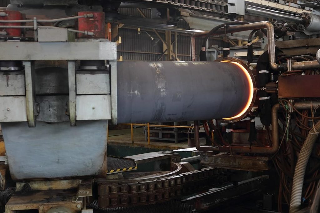
8.3 Induction Bending
Induction bending is widely used for industrial pipeline bends.
A narrow circumferential band of the pipe is heated by an induction coil while the pipe is moved through the bending machine.
The heated section is gradually formed into a curved shape.
Advantages include:
- Suitable for large-diameter pipes.
- Controlled bending geometry.
- Continuous curved sections.
- Reduced need for multiple welded segments.
- Suitable for manufacturing specified pipeline bends.
ASME B16.49 covers factory-made wrought steel buttwelding induction bends for transportation and distribution piping applications within its defined scope.
8.4 Mandrel Bending
Mandrel bending uses an internal support inserted into the pipe during bending.
The mandrel helps maintain the internal cross-sectional shape and reduces the risk of flattening and wrinkling.
It is particularly useful for relatively thin-wall pipes and tighter bending requirements.
The appropriate mandrel design depends on pipe diameter, wall thickness, material and bend radius.
9. Common Defects During Steel Pipe Bending
Improper bending conditions may result in several manufacturing defects.
9.1 Wall Thinning
Excessive stretching at the extrados reduces the remaining wall thickness.
This may affect pressure integrity and dimensional acceptance.
9.2 Ovality
Ovality occurs when the circular pipe cross-section becomes elliptical during bending.
It is commonly evaluated by comparing the maximum and minimum outside diameters.
A common expression is:
Ovality (%) = (Dmax − Dmin) / Dnom × 100
The applicable definition and acceptance criteria must be confirmed in the relevant standard.
9.3 Wrinkling
Wrinkles can develop at the intrados because of excessive compressive deformation.
They may affect flow characteristics, appearance and structural integrity.
9.4 Cracking
Cracks may form when the material experiences excessive tensile strain.
Potential contributing factors include:
- Insufficient material ductility.
- Excessively small bending radius.
- Surface defects.
- Incorrect heating conditions.
- Improper tooling.
9.5 Springback
Springback is the partial recovery of the original pipe geometry after the bending force is removed.
It may cause the final bend angle or radius to differ from the intended dimensions.
Manufacturers must account for springback when setting bending parameters.
10. Inspection Requirements for Finished Steel Pipe Bends
Inspection is essential to verify that the finished bend meets the required dimensional and material specifications.
10.1 Dimensional Inspection
Typical measurements include:
- Outside diameter.
- Centerline radius.
- Bend angle.
- Tangent length.
- Overall dimensions.
- Cross-sectional ovality.
10.2 Wall Thickness Measurement
Ultrasonic thickness testing is commonly used to measure wall thickness at the extrados, intrados and other specified positions.
The minimum remaining wall thickness is particularly important.
10.3 Surface Inspection
Visual inspection is used to identify:
- Cracks.
- Surface damage.
- Wrinkles.
- Buckling.
- Excessive oxidation.
- Other visible defects.
10.4 Nondestructive Testing
Depending on the applicable product specification and project requirements, inspection may include:
- Ultrasonic Testing (UT).
- Magnetic Particle Testing (MT).
- Liquid Penetrant Testing (PT).
- Radiographic Testing (RT).
The required examination method and coverage must be specified according to the applicable standard and project inspection plan.
10.5 Mechanical Testing
For certain induction bends and other critical products, mechanical testing may be required to verify that forming and heat treatment have not adversely affected material properties.
Testing may include tensile, hardness and impact tests, where specified.
11. Standards Related to Steel Pipe Bending Radius
Several standards and codes are relevant to steel pipe bending and finished bend inspection.
11.1 ASME B31.3 – Process Piping
ASME B31.3 provides requirements for process piping systems, including design, materials, fabrication, examination and testing.
Its bending provisions address the fabrication procedure and the acceptability of finished bends.
11.2 ASME B16.49 – Factory-Made Wrought Steel Buttwelding Induction Bends
ASME B16.49 covers factory-made induction bends for specified transportation and distribution piping applications.
It includes requirements relating to:
- Design.
- Materials.
- Manufacturing.
- Testing.
- Marking.
- Inspection.
It should not be treated as a universal specification for every type of pipe bend or process piping application.
11.3 ASME B31.4 and ASME B31.8
ASME B31.4 addresses pipeline transportation systems for liquids and slurries.
ASME B31.8 addresses gas transmission and distribution piping systems.
These codes provide relevant engineering requirements for pipeline design and construction.
11.4 Project Specifications
In addition to industry standards, individual projects may specify:
- Minimum bend radius.
- Maximum wall thinning.
- Maximum ovality.
- Bend angle tolerance.
- Heat treatment.
- Mechanical testing.
- Nondestructive examination.
The applicable code edition and project specification should always be confirmed before manufacturing.
12. How to Choose the Right Steel Pipe Bending Radius
Selecting a suitable bending radius requires a combination of dimensional, material and engineering considerations.
Before confirming a bending radius, buyers and engineers should evaluate:
- Pipe nominal size and actual outside diameter.
- Specified wall thickness and minimum permissible thickness.
- Material grade and mechanical properties.
- Required bend angle.
- Centerline radius and radius reference.
- Bending method.
- Internal pressure and service temperature.
- Corrosion and erosion allowances.
- Permitted wall thinning and ovality.
- Applicable engineering standards.
For example, a 6-inch carbon steel pipe and a 6-inch stainless steel pipe may require different bending procedures even when both are specified as 5D bends.
Similarly, a thin-wall pipe may require a larger radius or internal support compared with a thick-wall pipe of the same outside diameter.
The final radius should be confirmed through engineering assessment and, where necessary, a qualified bending procedure.
13. Frequently Asked Questions About Steel Pipe Bending Radius
What is the minimum bending radius of a steel pipe?
There is no single minimum bending radius applicable to all steel pipes. It depends on outside diameter, wall thickness, material properties, bending method and applicable engineering requirements.
What does 3D, 5D or 10D mean in pipe bending?
These designations describe the ratio between the centerline bend radius and the specified reference pipe diameter. For example, a 5D bend has a centerline radius equal to five times the reference diameter.
Is a 3D bend tighter than a 5D bend?
Yes. A 3D bend has a smaller centerline radius and tighter curvature than a 5D bend of the same reference diameter.
Which is better, a 3D or 5D pipe bend?
Neither is universally better. A 3D bend requires less installation space but generally involves more severe deformation. A 5D bend provides a larger radius and may reduce bending-related deformation.
Does pipe wall thickness affect bending radius?
Yes. Thin-wall pipes are generally more susceptible to ovality, wrinkling and local buckling. Wall thickness must be considered together with pipe diameter and material properties.
What is the difference between centerline radius and inside radius?
Centerline radius is measured along the pipe centerline, while inside radius is measured along the inner surface of the bend. They differ by half the outside diameter for an ideal circular bend.
Does pipe bending reduce wall thickness?
Yes. The extrados is stretched during bending, which causes wall thinning. The intrados experiences compression and may become thicker or develop wrinkles.
Which bending method is suitable for large-diameter steel pipes?
Induction bending is commonly used for large-diameter pipeline bends. The appropriate method depends on pipe size, wall thickness, material and project requirements.
What is the purpose of a mandrel in pipe bending?
A mandrel supports the inside of the pipe during bending and helps reduce flattening, ovality and wrinkling.
What is ASME B16.49?
ASME B16.49 is a standard covering factory-made wrought steel buttwelding induction bends for specified transportation and distribution piping systems.
How is pipe bend ovality measured?
It is commonly measured by comparing the maximum and minimum outside diameters at the same cross-section, using the definition and acceptance limits specified by the applicable standard.
14. Conclusion
Steel pipe bending radius is an important parameter in pipeline design, manufacturing and installation.
The selection of a suitable radius requires more than simply multiplying pipe diameter by a standard ratio. Outside diameter, wall thickness, material properties, bending angle, manufacturing method and service conditions must all be considered.
Common designations such as 3D, 5D and 10D provide a convenient way to specify bend geometry, but they do not establish universal minimum bending requirements.
During bending, the extrados experiences tensile deformation and wall thinning, while the intrados experiences compression and may develop wrinkles or buckling. Excessive deformation can also cause ovality, cracking and dimensional deviations.
For reliable performance, manufacturers should control bending parameters and verify the finished product through dimensional inspection, ultrasonic thickness measurement and other tests required by the applicable specification.
Looking for Steel Pipe Bends with Accurate Dimensions and Reliable Quality?
Whether you require 3D, 5D, 10D or custom-radius steel pipe bends, provide the pipe material grade, outside diameter, wall thickness, bend angle, centerline radius, manufacturing method and applicable project standard.
Request a quotation with dimensional inspection records, wall thickness measurements and relevant material test certificates.