
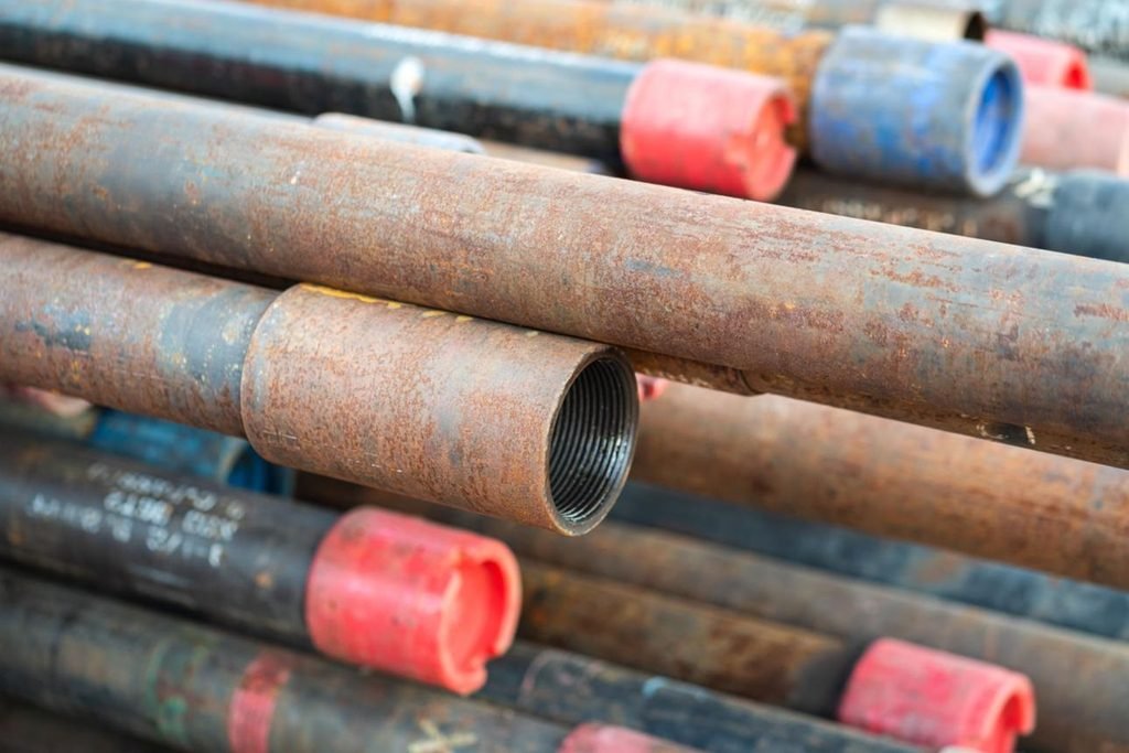
1. Why Is Oil Well Tubular Service Life Important?
Oil well tubulars are exposed to demanding operating conditions throughout drilling, completion and production.
Casing and tubing must withstand internal and external pressure, axial loads, temperature variations, corrosive fluids and mechanical wear. Over time, these conditions can cause material degradation, wall thickness reduction, connection damage and structural failure.
The most common tubular products used in oil and gas wells include:
- Surface casing.
- Intermediate casing.
- Production casing.
- Production tubing.
- Injection tubing.
Although these products are manufactured from high-strength steel, their service life depends on more than their initial mechanical properties.
Downhole environments may contain carbon dioxide (CO₂), hydrogen sulfide (H₂S), chlorides, formation water, sand and other aggressive substances. Mechanical contact with drilling tools, production equipment and moving components can also accelerate wear.
A well-designed tubular integrity management strategy should therefore focus on five main areas:
- Selecting suitable materials for actual downhole conditions.
- Controlling corrosion and chemical degradation.
- Reducing erosion and mechanical wear.
- Protecting pipe connections and maintaining installation quality.
- Conducting regular inspection and condition monitoring.
The objective is not simply to prevent pipe failure, but to maintain the required mechanical and pressure-containing performance throughout the intended service period.
2. Common Factors That Reduce Oil Well Tubular Service Life
Understanding the main failure mechanisms is the first step toward improving tubular reliability.
2.1 CO₂ Corrosion
Carbon dioxide corrosion is a common problem in oil and gas production systems.
When CO₂ dissolves in formation water, it forms carbonic acid and creates conditions that can accelerate steel corrosion.
The corrosion rate depends on several factors, including:
- CO₂ partial pressure.
- Temperature.
- Water chemistry.
- pH.
- Flow velocity.
- Water production rate.
- Protective corrosion product formation.
CO₂ corrosion may appear as relatively uniform wall thinning or localized attack.
Under certain conditions, iron carbonate (FeCO₃) corrosion products may form a protective layer on the steel surface. However, this layer is not always stable or sufficiently protective, particularly when flow conditions or water chemistry change.
If corrosion is not controlled, the remaining wall thickness may become insufficient for the required internal pressure and mechanical loads.
2.2 H₂S Corrosion and Sulfide Stress Cracking
Hydrogen sulfide is particularly important when selecting materials for sour-service wells.
H₂S can promote hydrogen entry into steel and increase the risk of hydrogen-related cracking mechanisms.
Potential damage mechanisms include:
- Sulfide Stress Cracking (SSC).
- Hydrogen-Induced Cracking (HIC).
- Stress-Oriented Hydrogen-Induced Cracking (SOHIC).
- Other forms of hydrogen-related cracking.
These mechanisms are influenced by material hardness, tensile stress, H₂S partial pressure, pH, temperature and water chemistry.
High-strength steel should not automatically be considered suitable for sour service.
Material selection must be assessed according to ISO 15156 / NACE MR0175 and the actual operating environment.
2.3 Chloride-Induced Corrosion
Formation water and completion fluids may contain significant concentrations of chloride ions.
Chlorides can contribute to localized corrosion and may increase the susceptibility of certain stainless steels and corrosion-resistant alloys to pitting and crevice corrosion.
At elevated temperatures, the risk of localized corrosion and chloride-related stress corrosion cracking may increase, depending on the material and environment.
The actual chloride concentration, temperature, pH and applied stress must be evaluated before selecting a corrosion-resistant material.
2.4 Erosion Caused by Sand and High-Velocity Fluids
Erosion occurs when flowing fluids carrying solid particles remove material from the pipe surface.
Common sources include:
- Formation sand.
- Proppant from hydraulic fracturing.
- Scale particles.
- Corrosion products.
- Other abrasive solids.
Erosion is particularly important in high-velocity production systems, gas wells and wells with significant sand production.
The damage may become more severe at elbows, restrictions, connections and locations where flow direction changes.
Unlike uniform corrosion, erosion can produce highly localized wall loss.
2.5 Mechanical Wear
Mechanical wear is caused by repeated physical contact between tubulars and other downhole components.
Typical sources include:
- Drill pipe rotation against casing.
- Tubing movement during production operations.
- Rod-string contact with tubing.
- Coiled tubing operations.
- Repeated tool movement.
- Casing contact in deviated and horizontal wells.
Wear may produce grooves, scratches and localized wall thinning.
In highly deviated wells, contact forces between the tubular string and wellbore can increase mechanical wear.
2.6 Fatigue Damage
Oil well tubulars may experience repeated loading during drilling, production, workover and pressure cycling.
Repeated changes in axial load, bending stress, internal pressure and temperature can contribute to fatigue damage.
Fatigue cracks may initiate at:
- Thread roots.
- Connection transitions.
- Surface defects.
- Corrosion pits.
- Areas with stress concentration.
- Manufacturing discontinuities.
Fatigue damage is particularly important in wells involving frequent intervention, cyclic injection or repeated pressure fluctuations.
2.7 Connection Leakage and Thread Damage
Connections are critical components of casing and tubing strings.
Improper handling, incorrect make-up torque, damaged threads or unsuitable connection selection can result in leakage and premature failure.
Common connection problems include:
- Thread galling.
- Cross-threading.
- Damaged thread crests.
- Insufficient make-up.
- Excessive make-up torque.
- Seal surface damage.
- Connection leakage.
A high-quality pipe body cannot compensate for an improperly installed or damaged connection.
3. How to Select the Right Materials for Longer Tubular Service Life
Material selection is one of the most effective ways to improve oil well tubular reliability.
The selected material must satisfy both mechanical requirements and environmental compatibility.
3.1 Carbon and Low-Alloy Steel
Carbon steel and low-alloy steel are widely used for oil well casing and tubing.
Common API 5CT grades include:
- J55.
- K55.
- N80.
- L80.
- P110.
- Q125.
These grades provide different mechanical strength levels and product requirements.
They are suitable for different operating conditions, depending on pressure, temperature, corrosion exposure and design loads.
However, higher yield strength does not automatically mean better corrosion resistance.
For sour-service applications, the material must meet the environmental requirements of the applicable ISO 15156 provisions.
3.2 Low-Alloy Steel for Sour-Service Applications
Certain controlled-hardness low-alloy steel grades may be suitable for sour-service applications when their material condition and environmental limits comply with the applicable standard.
L80 is commonly evaluated for sour-service tubing and casing applications.
However, the suitability of L80 depends on the specific grade type, hardness, H₂S partial pressure, pH, temperature and applied stress.
A grade designation alone is not sufficient to establish sour-service compatibility.
3.3 Corrosion-Resistant Alloys (CRAs)
Corrosion-resistant alloys are considered when carbon and low-alloy steels cannot provide sufficient corrosion resistance under the intended conditions.
Common materials include:
13Cr Stainless Steel
13Cr tubing is used in selected CO₂-containing production environments.
Its suitability depends on temperature, chloride concentration, CO₂ partial pressure, pH and other environmental factors.
Super 13Cr Stainless Steel
Super 13Cr grades provide enhanced corrosion performance in certain environments compared with conventional 13Cr.
Their use still requires environmental qualification.
Duplex Stainless Steel
Duplex stainless steels combine austenitic and ferritic microstructures.
They offer high mechanical strength and resistance to certain forms of corrosion, including chloride-related localized corrosion.
Nickel-Based Alloys
Nickel-based corrosion-resistant alloys may be selected for particularly demanding environments involving combinations of H₂S, CO₂, chlorides and elevated temperatures.
They generally involve higher material costs and require careful compatibility assessment.
3.4 Material Selection Comparison
| Material Family | Main Characteristics | Selection Considerations |
|---|---|---|
| Carbon Steel | Economical, widely available | Requires suitable corrosion management |
| Low-Alloy Steel | Higher strength options | Sour-service limits and hardness control |
| 13Cr Stainless Steel | Improved CO₂ corrosion resistance in selected environments | Chloride, temperature and H₂S limitations |
| Super 13Cr | Enhanced corrosion resistance in selected service conditions | Requires environmental qualification |
| Duplex Stainless Steel | High strength and localized corrosion resistance | Chloride and temperature assessment |
| Nickel-Based Alloys | Suitable for selected severe corrosive environments | High cost and detailed compatibility assessment |
The final material selection should follow the actual production-fluid composition and applicable material qualification requirements.
4. Effective Methods to Prevent Corrosion in Oil Well Tubulars
Corrosion prevention requires a combination of material selection, chemical treatment, operating control and inspection.
4.1 Corrosion Inhibitors
Corrosion inhibitors are chemicals introduced into production or injection systems to reduce the corrosion rate.
Many oilfield inhibitors work by forming an adsorbed protective film on the metal surface.
They may be applied through:
- Continuous chemical injection.
- Batch treatment.
- Squeeze treatment.
- Periodic chemical dosing.
The inhibitor must be compatible with the produced fluids, temperature, pressure and other completion chemicals.
Its effectiveness should be verified through corrosion monitoring rather than assumed from the injection rate alone.
4.2 Control of CO₂ and H₂S Exposure
The composition of produced fluids should be monitored to identify changes in corrosive conditions.
Important parameters include:
- CO₂ concentration and partial pressure.
- H₂S concentration and partial pressure.
- Produced water chemistry.
- pH.
- Chloride concentration.
- Water production rate.
- Operating temperature.
Where feasible, operational measures and suitable treatment programs can reduce corrosion risks.
However, chemical treatment cannot replace the requirement for an appropriately selected material in a severe sour-service environment.
4.3 Oxygen Control
Oxygen contamination can significantly accelerate corrosion in water-containing systems.
Potential sources include:
- Workover fluids.
- Completion fluids.
- Injection water.
- Maintenance operations.
- Improper storage and handling.
Deaeration, oxygen scavengers and controlled fluid handling may be used where appropriate.
4.4 Scale and Deposit Management
Scale and deposits can create localized corrosion conditions by forming deposits and concentration cells.
Common deposits include:
- Calcium carbonate.
- Barium sulfate.
- Strontium sulfate.
- Iron sulfide.
- Iron carbonate.
Scale management programs should be designed according to water chemistry and production conditions.
Regular monitoring and suitable scale inhibitors can help reduce deposition and associated integrity problems.
4.5 Protective Coatings and Linings
Internal coatings and linings can provide an additional barrier between the steel surface and corrosive fluids.
Potential coating systems include:
- Epoxy-based coatings.
- Phenolic coatings.
- Fusion-bonded epoxy systems.
- Other application-specific protective linings.
Selection should consider:
- Operating temperature.
- Internal pressure.
- Fluid chemistry.
- Abrasion resistance.
- Adhesion.
- Coating thickness.
- Compatibility with production chemicals.
Coatings should not be treated as a universal replacement for corrosion-resistant base materials.
Coating damage, poor adhesion or local disbondment may expose the underlying steel and create localized corrosion risks.
5. How to Reduce Erosion and Mechanical Wear
Corrosion is not the only cause of tubular wall loss.
Mechanical wear and erosion can also reduce the remaining wall thickness and pressure capacity.
5.1 Control Sand Production
Sand production can accelerate erosion, particularly in high-velocity production systems.
Possible control measures include:
- Sand-control completion design.
- Appropriate production-rate management.
- Gravel packing.
- Screen systems.
- Downhole sand-management equipment.
The appropriate solution depends on reservoir characteristics and production requirements.
5.2 Optimize Fluid Flow Velocity
High flow velocity can increase erosion, especially when abrasive particles are present.
Flow velocity and particle concentration should be evaluated when designing production tubing and surface flow systems.
Changes in production rate should also be considered when reviewing erosion risk.
5.3 Use Wear-Resistant Components
In wells involving significant mechanical contact, suitable wear-resistant components may reduce localized damage.
Examples include:
- Tubing protectors.
- Wear-resistant centralizers.
- Appropriate hardbanding on compatible drilling components.
- Wear-resistant sleeves.
- Qualified protective materials.
These components should be selected according to the actual contact conditions and should not introduce additional damage to the casing or tubing.
5.4 Optimize Well Trajectory and Tubular Placement
In deviated and horizontal wells, tubular contact forces may be higher than in vertical wells.
Well trajectory, dogleg severity, axial load and tubular movement should be considered during design.
Appropriate centralization and completion design may help reduce localized contact and wear.
6. How to Protect OCTG Connections and Prevent Leakage
Connection integrity is essential for maintaining the pressure containment of oil well tubular strings.
6.1 Select the Appropriate Connection Type
Common casing connections include:
- Short Thread and Coupling (STC).
- Long Thread and Coupling (LTC).
- Buttress Thread and Coupling (BTC).
- Premium connections.
Common tubing connections include:
- NUE.
- EUE.
- Premium connections.
Premium connections may offer enhanced sealing and combined-load performance when properly designed and qualified.
The selection should be based on pressure, axial loading, temperature, corrosion exposure and installation requirements.
6.2 Proper Thread Handling
Thread damage can occur during manufacturing, transportation, storage and field installation.
Recommended practices include:
- Use appropriate thread protectors.
- Avoid direct impact on threaded ends.
- Keep threads clean and dry.
- Inspect pin and box threads before make-up.
- Use compatible thread compounds.
- Follow the manufacturer’s make-up procedure.
6.3 Control Make-Up Torque
Incorrect make-up torque can cause connection leakage or damage.
Insufficient torque may result in incomplete engagement and inadequate sealing.
Excessive torque may cause thread deformation, galling or connection damage.
Make-up should follow the specified connection manufacturer’s procedures and torque-turn requirements.
6.4 Inspect Connection Sealing Surfaces
Premium connections may use metal-to-metal sealing surfaces.
These surfaces require particular care because small scratches, dents or contamination can compromise sealing performance.
Visual and dimensional inspection should be performed according to the connection specification.
7. The Importance of Regular Inspection and Maintenance
Inspection helps identify degradation before it develops into a major tubular failure.
The inspection program should be based on well conditions, failure history, risk level and applicable industry requirements.
7.1 Visual Inspection
Visual inspection identifies visible surface damage, corrosion, deformation and connection defects.
Typical inspection items include:
- External corrosion.
- Pitting.
- Mechanical damage.
- Thread damage.
- Connection deformation.
- Protective coating damage.
7.2 Ultrasonic Testing (UT)
Ultrasonic testing is used to evaluate wall thickness and detect certain internal discontinuities.
It can help identify:
- Localized wall thinning.
- Internal corrosion.
- External corrosion.
- Lamination.
- Other relevant defects.
For in-service tubular inspection, the inspection procedure must be suitable for the pipe geometry, surface condition and defect type.
7.3 Electromagnetic Inspection (EMI)
Electromagnetic inspection is commonly used for oilfield tubular inspection.
Depending on the equipment and procedure, it can identify certain metal-loss conditions and other discontinuities.
EMI is useful for evaluating tubing and casing condition, particularly when a full-length inspection is required.
Its capabilities and limitations should be understood when interpreting results.
7.4 Eddy Current Testing (ECT)
Eddy current testing uses electromagnetic induction to detect surface and near-surface defects.
It can be useful for identifying certain localized discontinuities.
The method is sensitive to material properties, geometry, probe configuration and inspection conditions.
7.5 Drift Testing and Dimensional Inspection
Drift testing verifies whether the pipe maintains the required internal clearance.
Dimensional inspection may include:
- Outside diameter.
- Wall thickness.
- Ovality.
- Straightness.
- Connection dimensions.
- Thread geometry.
These measurements help determine whether the tubular remains suitable for its intended application.
7.6 Connection Inspection
Connection inspection should include thread condition, sealing surfaces, coupling dimensions and evidence of previous damage.
Where necessary, qualified inspection procedures and connection-specific gauges should be used.
8. How to Monitor Remaining Wall Thickness and Tubular Service Life
Monitoring wall thickness is important because corrosion and erosion gradually reduce the effective load-bearing section.
A simplified estimate of remaining service life under uniform corrosion can be expressed as:
Remaining Life = (Current Wall Thickness − Minimum Required Wall Thickness) / Corrosion Rate
For example, consider a tubing section with:
- Current wall thickness: 9.0 mm.
- Minimum required wall thickness: 7.0 mm.
- Estimated corrosion rate: 0.20 mm/year.
The simplified remaining life is:
Remaining Life = (9.0 − 7.0) / 0.20
Remaining Life = 10 years.
This is only an illustrative uniform-corrosion calculation.
Actual tubular remaining life cannot be established using this equation alone because:
- Corrosion rates may change over time.
- Localized pitting may be more severe than average wall loss.
- Erosion and corrosion may occur simultaneously.
- Pressure and axial loads may change.
- Inspection uncertainty must be considered.
- Manufacturing tolerances and defect geometry affect remaining strength.
For critical tubulars, remaining strength and fitness-for-service assessments should use actual inspection data, appropriate mechanical models and qualified engineering procedures.
9. Establishing a Full-Life-Cycle OCTG Integrity Management Program
Extending tubular service life requires consistent management from procurement through final retirement.
9.1 Before Installation
Before running casing or tubing into the well, manufacturers, suppliers and operators should verify:
- API 5CT product specification.
- Steel grade.
- Chemical composition.
- Mechanical properties.
- Heat treatment condition.
- Dimensional tolerances.
- Nondestructive testing results.
- Connection quality.
- Material traceability.
A complete Material Test Certificate (MTC) and inspection documentation should be available.
9.2 During Installation
Installation quality has a direct influence on future tubular performance.
Important controls include:
- Correct handling and lifting.
- Thread protection.
- Connection cleaning.
- Proper thread compound application.
- Controlled make-up torque.
- Running speed management.
- Monitoring for abnormal loads.
9.3 During Production
Once the well is operating, monitoring should focus on:
- Produced water chemistry.
- CO₂ and H₂S conditions.
- Sand production.
- Pressure fluctuations.
- Temperature changes.
- Corrosion inhibitor performance.
- Annular pressure.
- Leakage indications.
Changes in production conditions should trigger a review of the existing integrity management plan.
9.4 During Workover and Maintenance
Workover operations provide opportunities to inspect and assess tubing condition.
Recovered tubulars should be evaluated for:
- Corrosion.
- Erosion.
- Wear grooves.
- Wall thickness reduction.
- Connection damage.
- Deformation.
- Fatigue-related defects.
Reuse decisions should be based on inspection results and the applicable acceptance criteria.
9.5 Data-Based Integrity Management
A reliable tubular integrity program should maintain historical records of:
- Material grade.
- Pipe dimensions.
- Installation depth.
- Connection type.
- Operating pressure.
- Operating temperature.
- Produced fluid composition.
- Corrosion monitoring data.
- Inspection history.
- Failure and repair records.
Comparing inspection results over time makes it easier to identify degradation trends and determine when additional maintenance or replacement is required.
10. Common Mistakes That Shorten Oil Well Tubular Service Life
Several preventable mistakes can lead to premature tubular failure.
1. Selecting Steel Grade Based Only on Yield Strength
High yield strength does not guarantee corrosion resistance or sour-service suitability.
2. Ignoring Actual Downhole Fluid Chemistry
CO₂, H₂S, chlorides and produced water can significantly affect material performance.
3. Treating Coatings as a Complete Corrosion Solution
Coatings may be damaged, detached or incompatible with operating conditions.
4. Ignoring Localized Corrosion
Average wall thickness measurements may not reveal the deepest corrosion pits.
5. Incorrect Connection Make-Up
Improper torque and damaged threads may lead to leakage and premature connection failure.
6. Delaying Inspection
Small defects can develop into serious integrity problems if inspection and corrective action are postponed.
7. Reusing Tubulars Without Proper Assessment
Previously used tubing and casing should not be returned to service without suitable inspection and fitness-for-service evaluation.
11. Frequently Asked Questions About Oil Well Tubular Service Life
What factors affect the service life of oil well casing and tubing?
The main factors include material grade, corrosion, erosion, mechanical wear, fatigue, temperature, pressure, connection quality and operating conditions.
How can CO₂ corrosion in oil well tubing be reduced?
Suitable measures include corrosion inhibitor injection, fluid chemistry monitoring, appropriate material selection, oxygen control and regular inspection.
What is the difference between CO₂ corrosion and H₂S corrosion?
CO₂ corrosion is commonly associated with carbonic acid formation and metal dissolution. H₂S can promote hydrogen-related damage, including sulfide stress cracking and hydrogen-induced cracking.
Is P110 suitable for sour-service wells?
P110 should not automatically be considered suitable for sour service. Its suitability depends on the specific H₂S environment, material condition, hardness and applicable ISO 15156 requirements.
Which material is suitable for corrosive oil and gas wells?
Carbon steel, low-alloy steel, 13Cr, duplex stainless steel and nickel-based alloys may all be considered depending on the actual environment. No single material is suitable for every corrosive well.
How does sand production affect tubing service life?
Sand particles carried by high-velocity fluids can erode the internal pipe wall, particularly at restrictions and locations where flow direction changes.
How often should oil well tubing be inspected?
There is no universal inspection interval. Inspection frequency should be determined by risk assessment, operating conditions, corrosion monitoring, historical failure data and applicable regulations.
What is the role of ultrasonic testing in OCTG inspection?
Ultrasonic testing can measure remaining wall thickness and identify certain internal discontinuities, helping assess tubular integrity.
Can oil well tubing be reused after removal?
Yes, in suitable circumstances. However, reuse must be based on inspection, dimensional verification, mechanical condition and the applicable acceptance requirements.
How can the remaining service life of oil tubing be estimated?
A preliminary estimate may use remaining wall thickness and measured corrosion rate. A reliable engineering assessment must also consider localized damage, pressure capacity, loading conditions and inspection uncertainty.
12. Conclusion
Extending the service life of oil well tubulars in complex downhole environments requires more than selecting high-strength steel pipes.
CO₂ corrosion, H₂S-related cracking, chloride corrosion, erosion, mechanical wear, fatigue and connection damage can all reduce tubular integrity during service.
The most effective approach combines appropriate material selection, corrosion control, wear prevention, connection protection and regular inspection.
API 5CT steel grades such as J55, N80, L80 and P110 provide different mechanical properties, but their suitability must be evaluated against actual well conditions and environmental requirements.
For demanding sour-service and HPHT wells, material selection should follow applicable standards such as ISO 15156, while inspection and remaining-strength assessments should be based on actual tubular condition.
A well-managed OCTG integrity program helps identify degradation early, reduce unplanned workovers, prevent premature failures and improve the long-term reliability of oil and gas production systems.
Looking for Reliable Oil Casing and Tubing for Demanding Downhole Applications?
Whether your project requires API 5CT J55, N80, L80, P110 or corrosion-resistant OCTG products, specify the material grade, outside diameter, wall thickness, connection type, operating temperature, pressure and production-fluid composition.
Request a quotation with material test certificates, dimensional inspection reports, mechanical test results and relevant quality documentation.